The built-in multi-channel partial discharge online monitoring device in the switch cabinet is a product developed by our company in response to the State Grid's "Technical Specifications for Live Detection of Electric Power Equipment", "General Technical Specifications for Online Monitoring Devices of Substation Equipment" and other related live detection technical requirements. The system adopts non-contact ultrasonic and transient ground wave partial discharge detection technology. It is suitable for real-time monitoring and abnormal alarm of partial discharge signals of metal enclosed complete switch cabinet products. It has high sensitivity, strong anti-interference performance, and multiple communication methods. Features.
Metal enclosed complete switch cabinet products are widely used in various factories, mines, power transmission and substations, etc. The safe and reliable operation of these switchgear determines the reliability and safety of power supply, and plays a decisive role in the power supply system. Since electrical equipment inevitably suffers from electrical performance, thermal performance, chemical performance and insulation degradation under abnormal conditions during long-term operation, the electrical insulation strength is reduced, partial discharge occurs, and then malfunctions occur, affecting the service life of the switch cabinet.
This system aims to deploy pre-sensors (non-contact ultrasonic, transient ground voltage) inside the switch cabinet and cooperate with the acquisition unit to monitor the partial discharge signal during the operation of the switch cabinet online in real time. By setting the test threshold, Spectrum analysis, discharge characteristic analysis, and data upload allow users to easily determine whether there is partial discharge in the equipment. Based on medium and long-term trends, potential fault hazards can be discovered earlier, turning the previous passive detection method into an active "defensive" one. Monitoring makes the use of switch cabinet products safer and more reliable, and also adds new technical highlights to the products.
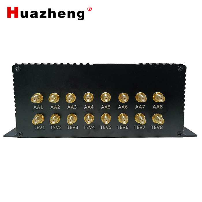
It adopts multi-channel design, suitable for simultaneous monitoring of multiple cabinets or multiple power monitoring in a single cabinet; supports multiple data transmission methods, such as RS485, network cable, LORA, etc.; supports multiple data protocols, such as Modbus, IP/TCP communication, etc.
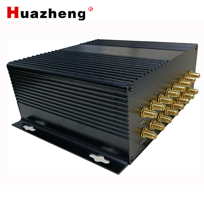
The system is mainly composed of ultrasonic, transient ground and ultra-high frequency three-in-one front sensors or ultrasonic and transient ground two-in-one front sensors, intelligent acquisition units, signal cables, etc. The front sensor is installed on the wall of the high-voltage chamber of the switch cabinet equipment through magnetic suction or positioning screws; the acquisition unit is arranged in the secondary room and connected to the front sensor through a signal line. Multiple front sensors can be connected and arranged in multiple switch cabinets. Or multiple monitoring circuits in a single switch cabinet. The acquisition unit filters and amplifies the front sensor signal, reduces noise, and performs analog-to-digital conversion to reach the range of AD conversion. The intelligent acquisition unit adopts high sampling rate and high resolution to collect the transient geomagnetic wave discharge signal and ultrasonic discharge signal coupled by the sensor, and the acquisition phase is strictly consistent with the external phase.
The collection units in each switch cabinet are connected to the data concentrator or third-party centralized control terminal through RS485, Lora or network cables, etc., and the data are transmitted to the local monitoring software or remote cloud platform. The software platform collects data based on each partial discharge collection unit. The discharge amount, polarity and time difference of the partial discharge are measured, and based on the statistical characteristics of the waveform of the partial discharge, compared with the corresponding parameters in the expert database, the partial discharge fault identification is obtained, and the degree of damage of the partial discharge is further judged.
The switch cabinet partial discharge online monitoring system is suitable for online monitoring of cables with voltage levels of 10KV and above and switch cabinet partial discharge online monitoring. It can monitor basic partial discharge parameters such as discharge amount, discharge phase, and number of discharges in real time; calculate partial discharge amplitude and frequency; and give an alarm when necessary. And statistics on relevant parameters can be provided according to customer requirements. It can store test spectra and discharge trends, and provide criteria for evaluating the insulation level and aging degree of high-voltage equipment in switch cabinets, and provide a basis for cable maintenance work.
Distributed layout, strong scalability
Monitor the network layout of terminals. When adding or removing terminals based on the original layout, the system automatically identifies and configures the terminals without additional settings.
real-time monitoring
The system records real-time data of each monitoring node, and the monitoring period can be flexibly set.
edge computing
The system has an in-situ digitization function: the acquisition device can digitize the partial discharge signal in-situ, which greatly simplifies data processing and ensures the accuracy of data transmission.
Various communication methods
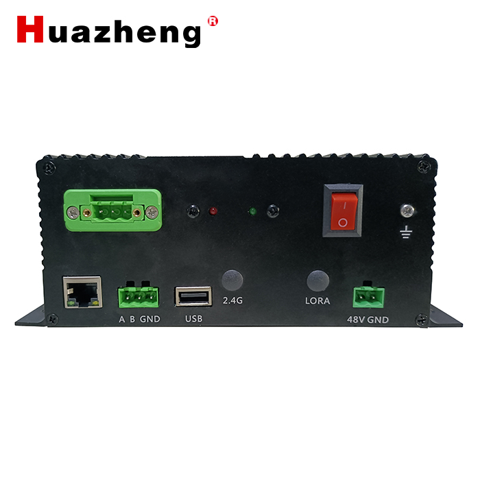
RS485, Lora or network cable can be used between the collection unit and the intelligent gateway to flexibly adapt to on-site conditions.
Various synchronization methods
External voltage synchronization and internal virtual synchronization.
Timely warning
When a node detects abnormal partial discharge, it will be quickly fed back to the monitoring server, and the server software will record necessary information and issue an alarm.
Impact resistance
It can withstand 600KV flashover impact without damaging the terminal equipment or losing data.
Anti-interference
Equipped with time domain and frequency domain signal analysis technology, it can effectively separate interference signals and partial discharge signals, and effectively avoid interference at the power supply end of the instrument.
marginal computing
In line with the current IoT terminal design concept, computing is marginalized, data is processed on-site, and analyzed off-site.
Interruption, data reproduction backtracking mechanism.
Transmission is stable
With the help of a powerful mobile network, data can be transmitted directly to the server remotely, with reliable transmission performance and low network delay.
Good access security
The access to the system does not affect the sealing and insulation performance of the switch cabinet, nor does it affect the safe operation of the equipment.
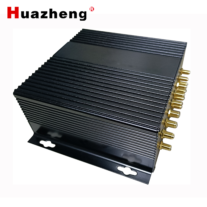
This partial discharge monitoring unit provides three partial discharge sensor detection methods: ultrasonic (AA), transient ground voltage (TEV), and ultra-high frequency (UHF). It is connected to the monitoring network through 485 or network cable and transmits data to the background.
Using the modbus 485/TCP protocol (default address 0x01), the data concentrator serves as a slave and is connected to the gateway device.
The gateway obtains the measurement information corresponding to the monitoring point through the 03 function code:
Register address | Monitoring value meaning | type of data | unit | Remark |
0 | Ultrasonic partial discharge peak | Short | dBuV | |
1 | Number of ultrasonic partial discharge discharges | Short | times | |
2 | Effective value of ultrasonic partial discharge measurement | Short | dBuV | |
3 | Ultrasound partial discharge diagnostic probability | Short | % | |
4 | Ultrasonic noise level value | Short | dBuV | |
5 | battery power | Short | % | Non-battery powered is 100 |
6 | Reserved items | |||
7 | Reserved items | |||
8 | Reserved items | |||
9 | Reserved items | |||
10 | Ground wave partial discharge peak value | Short | dBmV | |
11 | Number of partial discharges of ground waves | Short | 次 | |
12 | Effective value of ground wave partial discharge measurement | Short | dBmV | |
13 | Diagnostic probability of ground wave discharge | Short | % | |
14 | Ground wave noise level value | Short | dBmV | |
15 | battery power | Short | % | Non-battery powered is 100 |
16 | Reserved items | Short | ||
17 | Reserved items | Short | ||
18 | Reserved items | Short | ||
19 | Reserved items | Short | ||
20 | UHF partial discharge peak | Short | dBm | |
21 | UHF discharge times | Short | 次 | |
22 | UHF partial discharge measurement effective value | Short | dBm | |
23 | Diagnostic probability of UHF partial discharge | Short | % | |
24 | UHF noise level value | Short | dBm | |
25 | battery power | Short | % | Non-battery powered is 100 |
26 | reserve | |||
27 | reserve | |||
28 | reserve | |||
29 | reserve |
Reading of spectrum lattice data:
Register address | Monitoring value meaning | type of data | unit | remark |
500 | Ultrasonic partial discharge map lattice data | Short | dBuV | 50*50 array |
3000 | Temporary local discharge map lattice data | Short | dBmV | 50*50 array |
5500 | UHF partial discharge spectrum lattice data | Short | dBm | 50*50 array
|
Parameter register (can be modified through 06 function code):
Register address | significance | type of data | data unit |
100 | AA attention threshold | Short | dBuV |
101 | AA alarm threshold | Short | dBuV |
102 | TEV attention threshold | Short | dBmV |
103 | TEV alarm threshold | Short | dBmV |
104 | UHF attention threshold | Short | dBm |
105 | UHF alarm threshold | Short | dBm |
200 | 485MODBUS address | Short | 0,255except |
201 | Sensor number | Short | 1start |
202 | IP address high 2 bytes | Short | 0XC0A8 Such as(192.168.10.100) |
203 | IP address lower 2 bytes | Short | 0X0A64 Such as(192.168.10.100) |
ØScope of application
ØIt is suitable for online monitoring and diagnostic analysis of transient ground wave partial discharge signals and ultrasonic signals of various medium and low voltage switchgear equipment.
ØØEnvironmental conditions
Ambient temperature -25℃~70℃;
Relative humidity ≤90%;
ØØPower supply 方式
Acquisition unit: DC48V power supply;
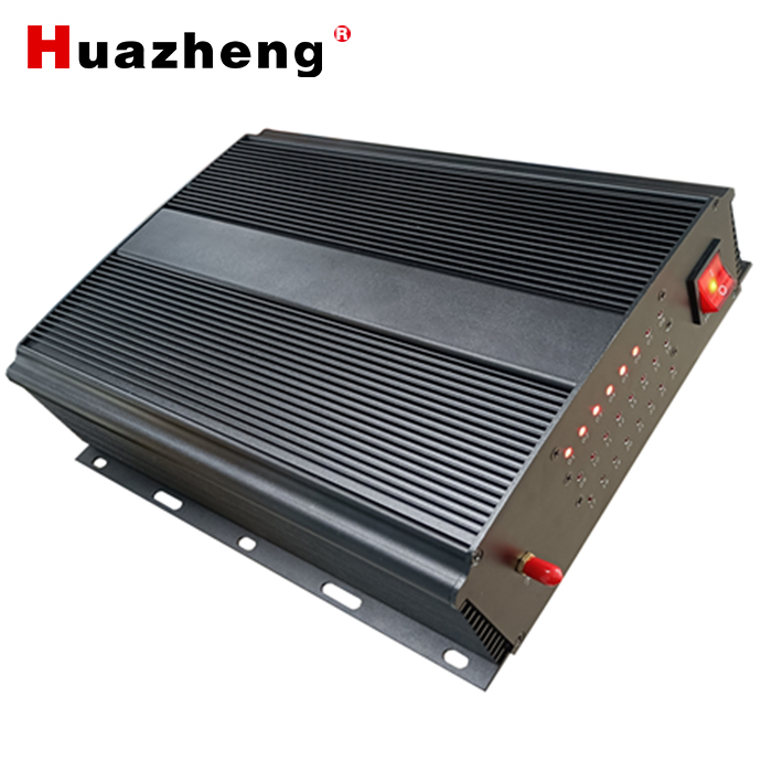
Online monitoring data concentrator (optional): external AC220V power supply;
ØTransient Earth Voltage Sensor (TEV):
Measurement range: 0 dBmV~70dBmV;
Detection frequency range: 3 MHz ~ 100MHz;
Linearity error: <±20%;
Øultrasonic sensor(AA):
Measurement range: -7dBuV~70dBuV;
Detection frequency range: 20kHz~200kHz
Linearity error: <±20%
ØUHF sensor:
Detection band: 300~1500MHz;
Detection sensitivity: -70dBm;
Measuring range: -80dBm~-10dBm
Øphysical size
Two-in-one sensor: 120*45*30 mm
Intelligent acquisition unit: 190*175*72mm
Online monitoring data concentrator: 250*230*80 mm

 中文
中文
 English

 +86-312-6775656
 +86 13731210226
 sales03@bdhuazheng.com
