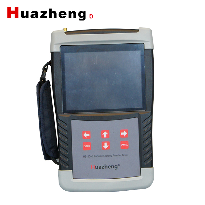
I.Overview
Zinc Oxide Arrester Comprehensive Tester is used to check the electrical performances of the zinc oxide arrester (MOA).The instrument is suitable for on-site inspection of zinc oxide arrester at all voltage levels, as well as the factory test and acceptance test in the library when power is failed.By measuring the full current and resistive current and other parameters,it can be found that it is possible to detect the dangerous defects such as the internal insulation of the zinc oxide arrester and the aging of the valve.
II.Functions And Fearutres
3.1 Being miniaturized and hand-held, small in size and light in weight, the instrument is easy to carry and operate.
3.2 Using a high-performance and low-power ARM processor with DSP floating-point processing units, the computing speed is faster, the operation accuracy is higher, and the processing data is larger. Thus, the accuracy and stability of the test data can be ensured.
3.3 High precision sampling filter circuit and digital filter technology can filter out the scene interference signal.
3.4 The floating-point fast Fourier algorithm is adopted to realize high precision analysis of the fundamental wave, harmonic voltage and current signal.
3.5 Using the industrial grade 5.6 inch 640 × 480 dot matrix high-brightness color LCD screen, it displays clearly and provides friendly man-machine interface; For some important operation and parameter settings, it displays the tips and help instructions; the top of the screen status bar can display each peripheral working status and test status information.
3.6 The electrical parameters of the three phase zinc oxide arrester can be measured at the same time, and the interphase interference can be compensated automatically. It can also be measured in single phase to support the PT secondary voltage of phase B as the reference voltage. The compensation angle can be automatically calculated when the measured phase and the reference voltage phase are different.
3.7 Provide both wired and wireless test methods, and wireless test mode operation is more simple and flexible which can greatly reduce the work intensity of the field test personnel.
3.8 The unique sensor board replaces the PT secondary voltage measurement technology, making the measurement safer and faster.
3.9 Voltage collector integrated local display (128 × 64 dot matrix OLED LCD screen) and phase sequence checking function can display three-phase full voltage, voltage fundamental wave, three, five and seven times harmonic RMS, system frequency values and three-phase voltage phase difference. It is easy for field testers to quickly check the connection between the voltage collector and PT secondary voltage output terminal and the parameters of the three-phase voltage.
3.10 The voltage collector adopts double digital isolation technology, which is more securer and reliable.
3.11 AC and DC: built-in lithium battery power supply or 220V AC charger power supplyself-adaptively.
3.12 With the built-in high-capacity rechargeable lithium battery inside the host and the voltage collector, the instrument can continuously work for 8 hours after a complete charge.
3.13 Intelligent battery management: the remaining power display, low power alarm, long idle reminder and backlight automatic regulation.
3.14 Built-in real-time clock can display the current time and date,and automatically record the test date and time.
3.15 The test data storage is divided into native storage and U Disk storage. The native storage can store 100 test data, and those date can be transferred into the U disk. U disk storage can save the test data and waveform pictures, with the test data in TXT format and the waveform picture in BMP format,which can be edited and printed directly on the computer.
3.16 The selected externalthermalprinter can print test data and the saved test record, and the printed content can be selected so as to save the paper.
III.Technical Index
3.1 Reference Voltage Measurement
3.1.1 Reference voltage input range: 25V~250V RMS,50Hz/60Hz
3.1.2 accuracy of reference voltage measurement: ± (reading × 5% + 0.2V)
3.1.3 accuracy of voltage harmonic measurement: ± (reading × 10%)
3.1.4 reference voltage channel input resistance: ≥1500kΩ
3.2 Current Measurement
3.2.1Whole current measurement range: 0 ~ 20mA RMS,50Hz/60Hz
3.2.2 Accuracy: ± (reading × 5% + 5uA)
3.2.3 fundamental wave measurement accuracy of resistive current: ± (reading × 5% + 5uA)
3.2.4 Current harmonics measurement accuracy: ± (reading × 10% + 10uA)
3.2.5 Current channel input resistance: ≤ 2Ω
3.3 Electric-field Intensity Measurement
3.3.1 input range of electric field strength: 30kV/m~300kV/m
3.3.2 accuracy of electric field intensity measurement:± (reading × 10%)
3.3.3 accuracy of electric field harmonic measurement: ± (reading × 10%)
3.4 Service Conditions And Shape
3.4.1 power supply:built-in lithium battery or external charger, charger input 100-240VAC 50Hz/60Hz,output DC8.4V 2A
3.4.2 Charging time: 4 hours
3.4.3 Battery life: host:8h, Voltage Collector: 8h
3.4.4 size of the host: 246mm (length) × 156mm (width) ×62mm (height)
3.4.5 weight of the host:1.0kg (excluding cables)
3.4.6 size of the voltage collector : 115mm (length) × 120mm (width) × 65mm (height)
3.4.7 voltage collector : 0.6kg (excluding cables)
3.4.8 service temperature: -10℃~50℃
3.4.9 relative humidity: <90%,No condensation