I.Security Warning
◆ The safety performance of this instrument complies with the IEC61010-1 standard.
◆ Please read this manual thoroughly before use and abide by the safety regulations and specification parameters in the manual during the test.
◆ During the insulation resistance test, there will be a dangerous voltage of up to 5kV on the test clip of the instrument; operators should not touch the circuit under test to avoid electric shock accidents.
◆ Before conducting insulation resistance test wiring, you must check and make sure that the tested product is in a power-off state.
◆ Before testing, it is necessary to check whether the withstand voltage value of the test line used matches the maximum output voltage value of the instrument used, so as to ensure the safety of testers and test accuracy.
◆ After starting the insulation resistance test, do not disconnect the test line from the tested object before the measurement is completed; otherwise, the tested object will not be discharged, resulting in the risk of electric shock.
◆ Do not test in a flammable place, sparks generated during the test may cause an explosion.
◆ It may be dangerous to perform insulation resistance test in a humid environment, and it is recommended not to conduct the test in this condition.
◆ Do not test if dirt or carbides that impair insulation properties are found on the test leads or the output ports of the instrument.
◆ When the instrument is abnormal or damaged, please stop using it immediately.
◆ This instrument is a special instrument with a certain degree of danger, please do not disassemble or repair it without authorization.
◆ The parameters of the built-in battery pack of the instrument are compatible with the performance parameters of the instrument. Users are not allowed to replace the battery by themselves to avoid abnormal operation of the instrument.
◆ The built-in battery pack of this instrument is a lithium-ion battery and a special charging circuit; when the instrument is not used for a long time, it should be charged once every 3 months to maintain the performance parameters of the built-in battery.
Note: Do not short-circuit the test line during the insulation resistance test; when short-circuited or disconnected, the tip of the test line will discharge. Excessive discharge may degrade the performance of the instrument.
II. Packaging Content
After you receive the shipping box, open the box and inspect it for damage. If the shipping container is damaged, or the instrument is damaged, please notify the shipping company and your nearest sales office of our company.
Please check that you received the following items in your kit:
Standard configuration:
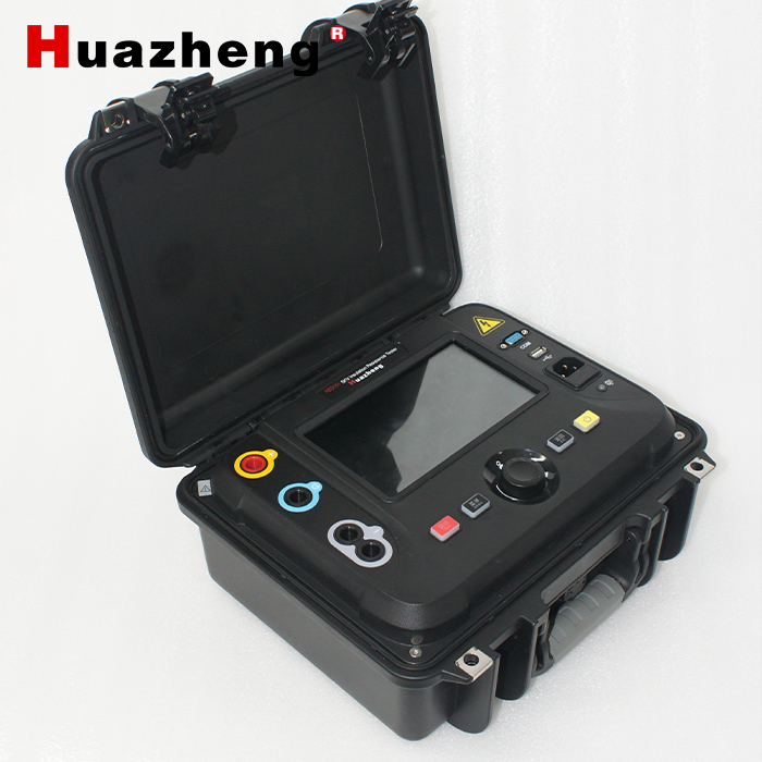
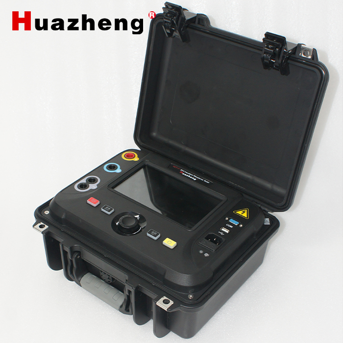
√1 tester
√1 set of test lines (1 red high voltage test line, 1 blue shielded protection line, 1 black shielded high voltage test line)
√1 three-core power cord
√3 250V/2A fuses
√1 printed user manual
√1 certificate and warranty card
√1 factory test report
III. Features
3.1 The fully isolated power supply scheme is adopted, and the low-voltage circuit (battery-powered, human-computer interaction operation circuit) is completely electrically isolated from the high-voltage circuit (NC high-voltage power supply, signal sampling circuit); the isolation voltage is as high as 30kV, thereby ensuring the safety of operators.
3.2 It adopts an industrial-grade 7-inch color LCD screen with a high resolution of 1024×600, a viewing angle of 85°, and a brightness of 400cd/m 2 ; it adopts a capacitive touch screen of explosion-proof glass, which has a good operating feel and a durable display.
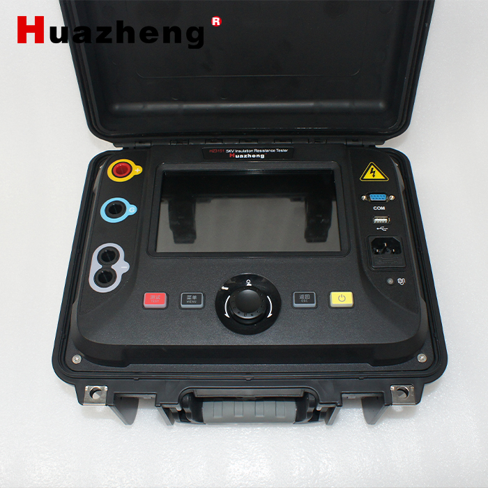
3.3 It has a single-button shuttle function + buttons with color backlight, giving operators a better operating experience.
3.4 With 6 voltage ranges:
100V, 250V, 500V, 1000V, 2500V, 5000V.
Custom voltage mode 50V ~ 5000V continuously adjustable, step voltage 10V.
3.5 The maximum output short-circuit current is 6mA; and 1mA, 2mA, 3mA, 4mA, 5mA, 6mA are adjustable.
3.6 The maximum continuous output power is 25W.
3.7 With an independent discharge circuit, it can quickly discharge the test product after the test is completed.
3.8 It has the test functions of insulation resistance IR, absorption ratio DAR, polarization index PI, dielectric discharge rate DD and step voltage SV.
3.9 Support R600s/R30s and R600s/R15s two DAR absorption ratio calculation modes.
3.10 It has the functions of DC and AC voltmeters, can automatically identify DC voltage and AC voltage signals, and can measure the frequency of AC voltage signals.
3.11 It has the function of measuring cable length.
3.12 With controllable hardware filter and software filter, the anti-interference performance of the instrument is greatly improved.
3.13 The test time in various test modes is saved independently and does not affect each other, which is convenient for the next use.
3.14 It has the functions of automatic shutdown of the instrument when it is idle and automatic shutdown when the battery is low, and the automatic shutdown time can be set.
3.15 With USB storage function, test data can be exported to USB in batches; and it supports the function of upgrading the main control firmware and high-voltage power supply firmware through USB.
3.16 It has RS232 (optional RS485) communication interface.
3.17 With Bluetooth communication function.
3.18 Built-in large-capacity lithium battery and built-in fast charger; both the instrument panel and LCD screen can indicate the current charging status.
IV. Technical Indicators
Insulation resistance measurement, test voltage 5kV: | |
Resistance range | resolution |
0~9.99kΩ | 0.01kΩ |
10.0~99.9kΩ | 0.1kΩ |
100~999kΩ | 1kΩ |
1.00~9.99MΩ | 10kΩ |
10.0~99.9MΩ | 100kΩ |
100~999MΩ | 1MΩ |
1.00~9.99GΩ | 10MΩ |
10.0~99.9GΩ | 100MΩ |
100~999GΩ | 1GΩ |
1.00~9.99TΩ | 10GΩ |
Note: The full-scale resistance value is related to the test voltage , and it can be calculated by referring to the following formula:
The unit of Ω is Ω, and the unit of Ω is V.
Under each test voltage, the relationship between the resistance test accuracy and the full-scale resistance | |||||
Resistance range | precision | ||||
| ±5% | ||||
| ±20% | ||||
The full-scale resistance value corresponding to each test voltage | |||||
Test voltage | Full scale resistance value | ||||
100V | 200GΩ | ||||
250V | 500GΩ | ||||
500V | 1.00 TΩ | ||||
1000V | 2.00 TΩ | ||||
2500V | 5.00 TΩ | ||||
5000V | 10.0 TΩ | ||||
testing time | |||||
Setting range | Adjustable from 10 seconds to 99 minutes | ||||
Test power | |||||
Fixed test voltage | 100V, 250V, 500V, 1000V, 2500V, 5000V | ||||
Custom Test Voltage | 50V~5000V The minimum step voltage is 10V. When using the single-button shuttle control, the step voltage value will automatically switch between 10V, 100V, and 200V with the speed of the shuttle. The higher the speed, the higher the step voltage value. | ||||
Voltage output accuracy | 0%~+10% | ||||
short circuit current | 1mA~6mA, adjustable, step 1mA | ||||
Short-circuit current accuracy | ±5% | ||||
continuous output power | 25W | ||||
Voltmeter | |||||
Measuring range | AC/DC 10V~660V, ±(2%+3 characters) | ||||
AC voltage frequency | 25Hz~85Hz, resolution 0.1Hz, accuracy ±0.2Hz | ||||
Output voltage measurement | |||||
precision | ±(2%+3 words) | ||||
Capacitance measurement | |||||
Measuring range | 10nF~25uF, test voltage ≥100V | ||||
precision | ±10%±5nF | ||||
Capacitance sample discharge rate | |||||
discharge rate | From 5kV to 50V, ≤0.47s/uF | ||||
Conditions of use and shape | |||||
AC power | 85~264Vrms, 50/60Hz, 65VA | ||||
Built-in battery | 16.8V, 4400mAH lithium battery | ||||
built-in charger | 16.8V 2.3A | ||||
battery life | 5kV@100MΩ load, about 6 hours | ||||
Dimensions | 320mm (length) × 270mm (width) × 150mm (height) | ||||
weight | 3.9kg | ||||
Operating temperature | -10℃~50℃ | ||||
Relative humidity | <90%, no condensation | ||||

 中文
中文
 English

 +86-312-6775656
 +86 13731210226
 sales03@bdhuazheng.com
