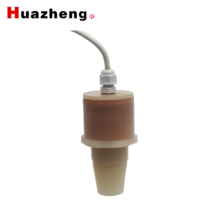
I.Electronic interface and signals definition
Cable color | Pin | Description | Note |
Red | 1 | Power supply | |
Black | 2 | GND | |
Yellow | 3 | Analogue output | The 600B will work in mode 1 or 0 cannot work in power save mode, if the 4-20mA, 0-3.3V 0-5V analogue output used. |
Blue | 4 | RS485A+ | TTL-TXD for ttl output signal |
Green | 5 | RS485B- | TTL-RXD for ttl output signal |
For switch output
Cable color | Pin | Description | Note |
Red | 1 | Power supply | |
Black | 2 | GND | |
Yellow | 3 | Switch output | Load current 1A@60V |
White | 4 | Switch output | |
Brown | 5 | RS485A+ | TTL-TXD for ttl output signal |
Green | 6 | RS485B- | TTL-RXD for ttl output signal |
II.Parameter
Sensing range | 600... 5000 mm@3.3V power supply. The measure distance can reach 6 meters if the power supply is 24V. |
Adjustment range | 300….5000mm |
Unusable area | 0 ... 600 mm |
Response delay | approx. 10 ms |
Operating voltage UB | 3.3 ... 24 V DC , ripple 10 %SS |
No-load supply current I0 | ≤ 20 mA active period and ≤0.3mA during sleep time |